Lets get your Rutland working…
The following are electrical tests that require the equipment below:
Multimeter


Test 1 - Test the Shutdown of the Turbine using the Regulator Switch.
Whilst the turbine is turning shutdown the turbine using the switch on the regulator. Perform this test in low to mid windspeeds.
| Result A | Conclusion / Next Action | |
| Slows to an idle and does not pick up with stronger winds. | This indicates there is a circuit between the regulator and turbine | If in doubt continue to Test 2 |
| Result B | Conclusion / Next Action | |
| Turbine continues to rotate without any change | This indicates there is not a circuit between the regulator and turbine |
|
Coming Soon
Test 2.1 - Open Circuit Voltage Check with the Turbine Installed
Test the open circuit voltage of the turbine.
Steps:
- Use a multimeter set to DC Volts to a level <20V if possible.
- In low winds shutdown the turbine using the regulator switch. Remove the turbine output cables at the regulator and connect the positive ‘+’ to the multimeter ‘+’ and turbine negative ‘-‘ to the multimeter ‘-‘.
| Result A | Conclusion / Next Action | |
| A varying DC voltage is observed in line with wind speed. | In low winds open circuit voltages up to 20V DC will typically be seen. Higher voltages in stronger winds can be seen. Note: never connect a spinning turbine or uncovered solar panel to a controller or damage may occur. | Confirmation that the turbine is operating correctly. It does not confirm that the connecting cable is capable of carrying current. Check the condition of the cable, the ends may appear to be in good condition but old cables may have unseen internal breakages. |
| Result B | Conclusion / Next Action | |
| Zero voltage reading is observed | Further investigation required | Check the condition of the cable, the ends may appear to be in good condition but old cables may have unseen internal breakages. If the cables are not damaged proceed to Test 2.2 |
Test 2.2 - Open Circuit Voltage Check with the Turbine Dismounted and on a Work Surface
Test the open circuit voltage of the turbine at cables that directly exit the turbine i.e. remove the connecting cables. For ease of handling remove blades to perform this test.
Steps:
- Use a multimeter set to DC Volts to a level <20V.
- Connect turbine output positive ‘+’ to the multimeter ‘+’ and turbine output negative ‘-‘ to multimeter ‘-‘. Spin the wind generator hub by hand as fast and safely as possible.
| Result A | Conclusion / Next Action | |
| A varying DC voltage is observed in line with hub speed. | Open circuit voltage when spinning fast by hand is typically 8-10V. | Confirmation that the turbine’s generator is operating.
|
| Result B | Conclusion / Next Action | |
| Zero voltage reading is observed | Further investigation required | Check brush gear, see Test 3 |
Coming Soon
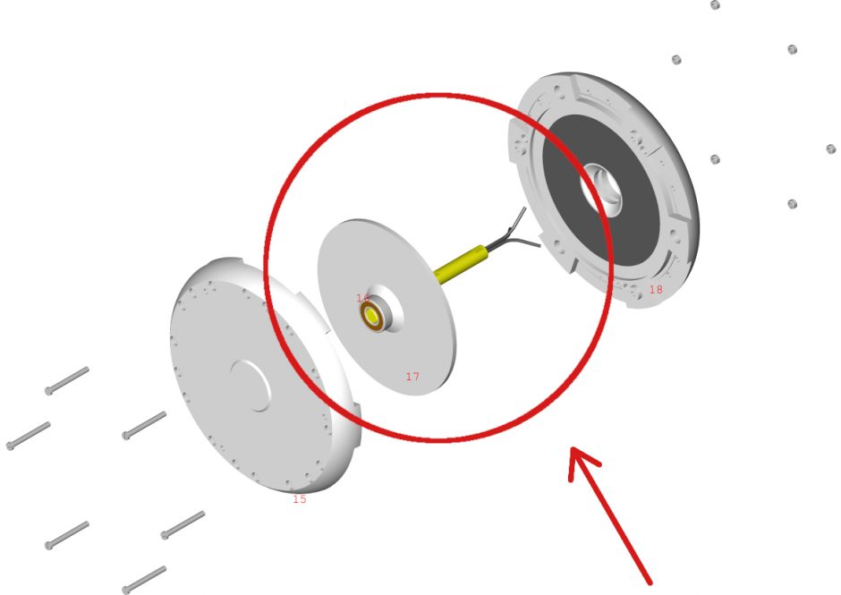
Test 3 - Check The Brush Gear with Turbine Dismounted and on a Work Surface
Remove necessary outer parts to access the brush gear (see exploded view below that shows where this is located)
Note: Later 914i models have 2 sets of brush gear
Steps
- Remove the 4 brush holder retaining screws to release the brush gear.
- Check that the springs move freely in the holders and the tension of the brush springs is good so that pressure is maintained onto the slip ring.
- Remove any dirt deposits around the carbon brush which can cause high resistance and low power production. Use fine sand paper to do this.
- Using fine sand paper apply light pressure onto the slip rings and rotate them from the post adaptor to clean away any carbon deposits.
- Change brushes as required and re-instate to return to operation.
Note: Heavy carbon deposits on brush gear is usually an indication of a reverse polarity connection in the wiring system, even momentarily and it could be a recent or historic event. Take care to observe polarity when making connections and avoid further damage.
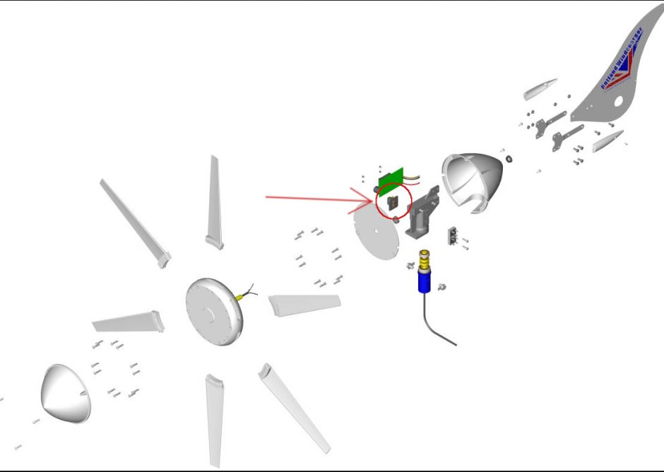
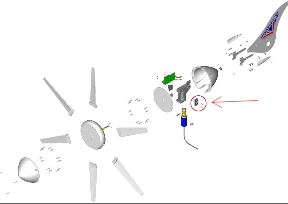
Test 4 - Inspect and Test The MPPT Circuit Board (pcb) with Turbine Dismounted
In a fault condition the MPPT will cause the turbine to stall. (see exploded view below that shows where the MPPT Circuit board is located)
- Use a multimeter set to continuity testing. Test across each pair of the MOSFET pins, if continuity is displayed the MPPT is faulty and requires repair or replacement.
The Rutland 914i can temporarily operate without the MPPT PCB until a replacement is fitted, in this mode performance will be reduced . (See second half of video for how to install new MPPT PCB). Follow these steps to bypass the MPPT temporarily and enable service to continue:
- Remove the PCB cable from the bottom carbon brush and split the joined cable.
- Remove the RED PCB cable from the top carbon brush.
- Remove final BROWN PCB cable from the rectifier.
- Cut the BROWN cable off the PCB and keep to one side.
- Connect BLACK cable from DC output of the rectifier to the bottom brush.
- Fix spare connector to the cut off BROWN cable and use this cable to connect between top brush and DC output on rectifier.
- Finally unscrew and remove the PCB.
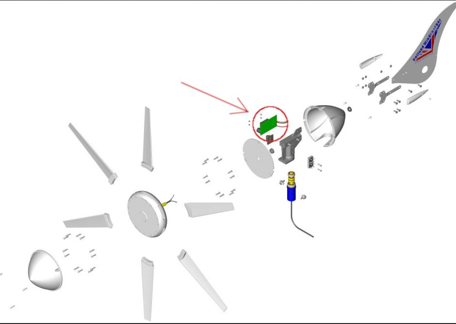
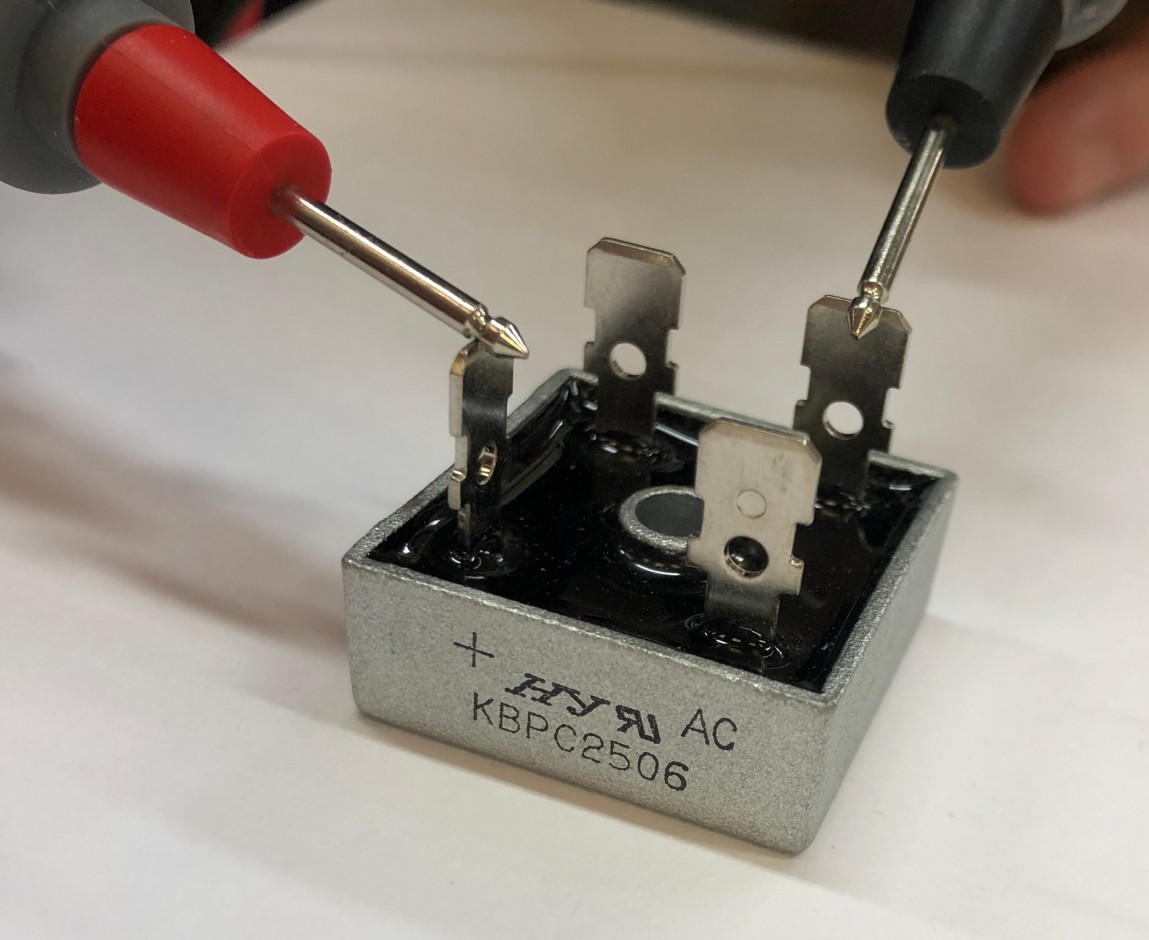
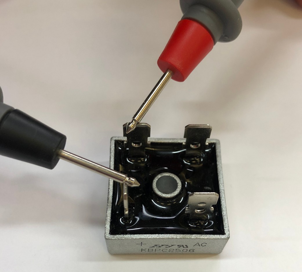
Test 5 - Check The Rectifier with the Turbine Dismounted and on a Work Surface.
To test the rectifiers it is necessary to remove all connections (see exploded view below that shows where these are located)
Note: We suggest you take a photograph to record the connections beforehand.
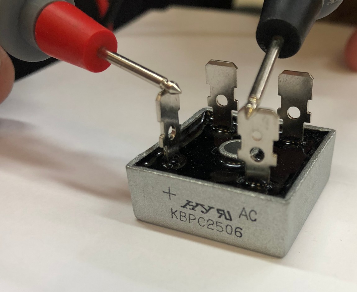
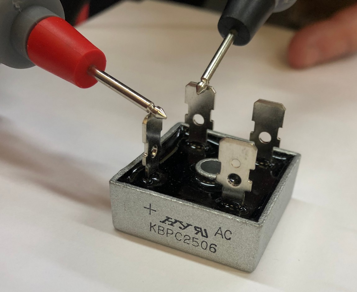
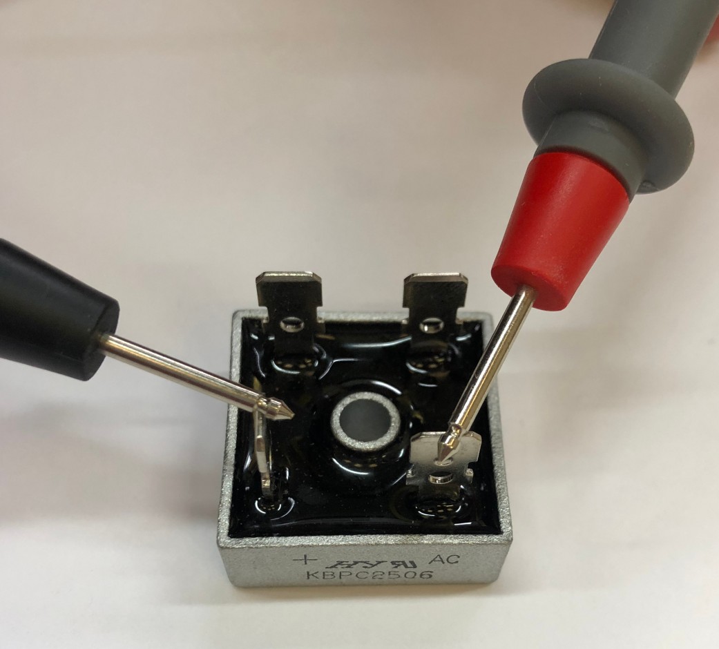
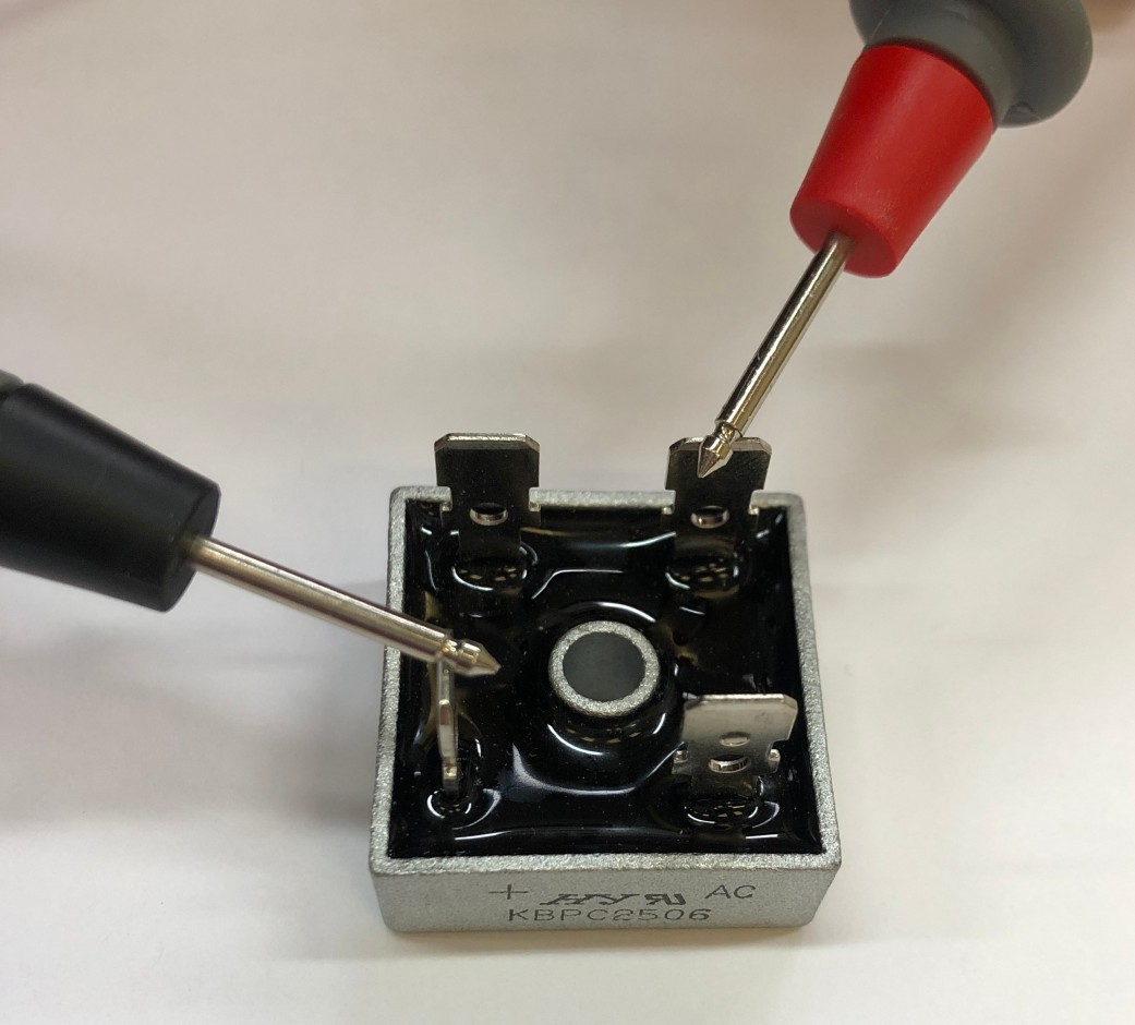
Identify the ‘+’, ‘-‘ and ‘AC’ positions on each rectifier.
Using a multimeter set to Diode Check measure between the positions shown in the table. If Diode Check is not available run the test for continuity, Multimeter Set to Ohms, however this is not the most definitive of tests owing to the types of multimeter in the market. If the diode check results are as below there is no need to test continuity. Where necessary purchase a new rectifier here
| Test | Multimeter Set at Diode Check | Multimeter Set to Ohms |
|
RED cable to ‘+’ rectifier terminal , BLACK to each AC terminal. |
No reading | No continuity |
|
BLACK cable to ‘+’ rectifier terminal, RED to each AC terminal. |
Reading | Continuity |
| RED cable to ‘-‘ rectifier terminal, BLACK to each AC terminal. | Reading | Continuity |
| BLACK lead to ‘-‘ rectifier terminal, RED to each AC terminal. | No reading | No continuity |
Coming Soon
Test 6 - Check The Stator Winding with the Turbine Dismounted and on a Work Surface.
Identify the 3 identical wires exiting the stator winding shaft (see exploded view below that shows where this is located). During this test take care not to allow any movement of the stator winding or magnets to avoid incorrect readings.
Note: We suggest you take a photograph to record the connections beforehand.
Steps:
- Disconnect the wires
- Using a multimeter on Ohms range measure the resistance levels across any 2 of the 3 leads and note the measurement.
- Repeat the procedure for each combination of 2 leads.
| Result A | |
| The readings should be approximately the same. |
The specific readings for your turbine should be 12V model = 0.8 Ohms, 24V model = 3.2 Ohms |
| Result B | |
| The readings don’t match the readings shown in Result A |
Replace the faulty Stator Winding 914i here If one or both of the magnets are damaged replace the complete hub assembly here |